
120 Years of Television
(German original "70 Jahre Fernsehgeräte" by Dipl.-Phys. Uwe Gebranzig - published in DPMA-Erfinderaktivitäten 2001).
This report presents an overview of important inventions in the field of television technology and provides patent literature explaining how the inventions were put into practice.
Paul Nipkow
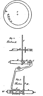
On Christmas Eve 1883 in Berlin, mathematics and science student Paul Nipkow had an idea which laid the foundation for today's television. His idea was to divide an image into lines at the transmitter and reconstitute the picture line-by-line at the receiver. Paul Nipkow filed a patent application for the invention at Kaiserliches Patentamt in Berlin, in 1884. In January 1885, he was granted the patent 30105 [1, 2, 3].
To put his basic concept into practice technically, Paul Nipkow suggested to use a rotating disk (Fig. 1) with a spiral pattern of holes (Nipkow disk) that scanned the image of a scene by dividing it line-by-line into small points, like a mosaic. The signals of the points, created at the transmitter, were sent to the receiver, reconstituting the pictures of the original scene, by a second spinning disk, punctured with a spiral of holes and synchronised with the first disk. The signals were generated at the transmitter by a photo-sensitive cell, positioned behind the first Nipkow disk, which controlled the brightness of a light source at the receiver. It was possible to view the light from this source passing through the second Nipkow disk.
Boris Rosing
As the rotating Nipkow disks had to be synchronised it was very difficult to translate Paul Nipkow's idea into practice, particularly at the receiver end.
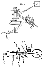
In 1907, the physicist, Boris Rosing, who worked in St. Petersburg, solved this problem by a television system [2], using an all-electronic, easy-to-synchronise image reproduction.
Since a rotating mirror drum was used to scan the image, image scanning at the transmitter was still a mechanical process. However, for reproducing the image Rosing already used a cathode ray tube or Braun tube. This picture tube, invented by the physicist Karl Ferdinand Braun in 1897, was capable of operating inertia-free. This type of cathode ray tube is still commonly used today as television picture tube.
This shows that, as early as 1907, Boris Rosing suggested an all-electronic television receiver - which is still commonly used today.
Manfred von Ardenne
In 1926, the 19-year-old Manfred von Ardenne invented the triple tube that reduced the price of a radio to one-third of its original price. At the age of 23, he came up with the idea of using a fast flying spot generated by the Braun tube for scanning images [1, 2, 3, 4, 5, 6, 7].
On Christmas Eve 1930 he achieved the first all-electronic television transmissions with Braun tubes at the transmitter and at the receiver [2].
At the 1931 Berlin Broadcasting Trade Fair, Manfred von Ardenne presented his all-electronic television transmissions to the public.
According to Walter Bruch, the inventor of colour television, that event was the world premiere of today's TV technology with electron beams [7].
The year 1931 marks the beginning of today's electronic television sets [4,6].
Due to their simplicity the flying-spot scanners are even today used for scanning films [4, 6].
DE 4310325A1 describes a flying-spot scanner for motion pictures which corresponds to the idea of Manfred von Ardenne (Fig. 3). The moving spot of light of a cathode ray tube scans the images of a motion picture film, across a scanning area on the fluorescent layer, located on the inside of the front screen of a cathode ray tube. The light passing through the film is captured by photomultipliers via associated dichroitic mirrors so that the photomultipliers produce output signals in the three primary colours: red, green and blue. After analog/digital conversion the output signals are transmitted to an image storage from which television images can be retrieved that correspond to the motion picture images.
Vladimir Kosma Zworykin
Using a Braun tube and a photo-sensitive cell at the transmitter, the flying-spot scanner by Manfred von Ardenne is particularly suitable for the TV transmission of photographic transparencies and motion picture films [4, 6], but for the television transmission of a TV announcer, the interaction of the Braun tube and the photo-sensitive cell requires complex technical provisions [5].
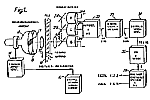
In 1933, Vladimir Kosma Zworykin, a student of Boris Rosing, invented the now common iconoscope, whose mode of operation corresponds to that of the human eye. This marked the triumph of television [2, 6, 8, 10].
Based on the photo effect, the iconoscope (Fig. 4) generates a charge image of the scene to be recorded, which is scanned by an electron beam [8].
All electronic cameras of today are still based on the principle of generating a charge image of the scene to be recorded that is subsequently scanned [8, 10, 13].
Henry de France
Another great progress in TV technology was colour television, introduced by the NTSC, the SECAM and PAL systems [9, 10, 11, 12, 13, 15].
These systems use two colour signals to modulate colour carriers. The modulation products generated are then added to the luminance signal.
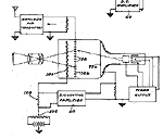
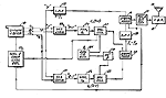
In 1953, the NTSC system (NTSC = National Television System Commitee) was introduced, a joint achievement of several American companies. In NTSC transmitter, the amplitudes of two colour carriers differing in phase by 90° are modulated by the colour signals of each line (Fig. 5). This modulation is known in communication technology as quadrature amplitude modulation (QUAM). The amplitude of the signal produced determines colour saturation and the phase determines hue [9, 11, 13, 15].
The unmodulated colour carrier is transmitted between the lines as a reference signal to help recover the colour signals from the quadrature modulated colour carrier at the receiver (Fig. 6).
Due to the frequent colour sub-carrier phase errors occurring during the transmission of the colour signal, the NTSC system may result in unnatural hues, spoiling the image displayed.
The susceptibility to phase errors of the NTSC system, resulting from quadrature amplitude modulation of the colour carrier, prompted scientists to develop other colour television transmission systems.
The French physicist, Henry de France, invented a process insensitive to NTSC phase shifts by transmitting one colour signal after the other on alternate lines instead of sending both colour signals together, the method used in the NTSC system (DE-AS 1044154, US patent 2993086).
In the SECAM system, it is sufficient to transmit only one of the colour signals in each line since colour information in two adjacent lines tends to change very little and the human eye does not notice a minor degree of reduction in colour resolution.
In order to obtain complete colour information for each line for displaying the image, the SECAM system combines the colour signal from adjacent lines by using a delay line functioning as a memory device (SECAM = séquentiel couleur à mémoire).
More detailed information on the SECAM system can be found in the literature [9, 11, 12, 13, 15].
Since SECAM uses frequency modulation of two colour carriers at different frequencies to transmit colour signals, the SECAM decoders in the receiver contain frequency discriminators for the demodulation of the colour carriers.
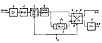
DE-OS 2113937 shows a SECAM decoder (Fig. 7) which has a single discriminator for the demodulation of the frequency modulated colour sub-carriers. (Frequency modulation is used to encode colour signals on the colour sub-carriers.) For this purpose the discriminator is switched from line to line to the relevant colour carrier frequency. A delay line downstream from the discriminator is used to delay the colour signals by one line, simulating simultaneity of the sequentially transmitted SECAM colour signals in the receiver [9]. This method ensures that the colour signals of successive lines are simultaneously available at the output of the SECAM decoder [13].
Walter Bruch
Walter Bruch improved on the NTSC system by measures applied at the transmitter end and the receiver end. While maintaining the quadrature amplitude modulation of the colour sub-carrier, he compensated the colour sub-carrier phase error occurring during NTSC transmission by transforming them into hardly noticeable colour saturation errors [9, 13, 15].
In 1962, Walter Bruch achieved this improvement with his PAL system. The phase of one of the two colour sub-carriers is inverted by 180° on every other line during encoding and the colour signals of the adjacent lines are combined at the decoding stage to compensate for colour phase errors (DE-PS 1252731).
The name PAL (phase alternation line) refers to the fact that the phase of the colour carrier is reversed on alternate lines.
The great advantage of the PAL system is that it avoids the NTSC system's sensitivity to phase changes by a minor modification, while achieving high colour fidelity.
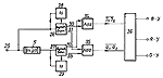
The PAL decoder (Fig. 8), described in DE-PS 1252731, adds the colour signals of successive lines and cancels out phase errors, by using a delay line, which serves as a line storage device, and two adders.
At the Broadcasting Trade Fair in Berlin, in August 1967, the PAL system was introduced in the Federal Republic of Germany and West Berlin [2, 3].
The PAL system is the prevalent colour TV system in more than 65 countries in the world owing to its excellent colour stability.
Eduard Schüller
The introduction of television gave rise to the demand for recording TV images.
Eduard Schüller had presented the world's first audio recorder in Berlin in 1935. In 1953 he invented the helical scan recording, a television recording principle. Today almost all video recorders (VCRs) operate on this recording principle [1, 2].
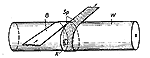
DE-PS 927999 shows an apparatus for the magnetic recording and reproduction of television images (Fig. 9.). A slow moving magnetic tape is helically wrapped around a rapidly rotating drum with a read/write head. Thus the moving magnetic tape is recorded and scanned by the read/write head along diagonal tracks (helical scan recording).
As helical scan recording is reliable and cheap it is widely used in the private sector and also in broadcasting stations all over the world [8, 14].
Benno Jahnel
When programming a VCR to automatically record a programme the problem often arises that the programme does not start at the time listed in the TV guides.
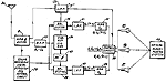
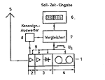
In 1976, Benno Jahnel suggested a new television transmission system to solve this problem. This system transmits a signal with each TV programme which identifies this TV programme. This identification signal will set the programmed VCR to start the recording.
The decisive idea of Benno Jahnel (Fig. 10) is that the identification signal contains the previously listed start time for the relevant programme independently of the actual broadcasting time of the programme and that the identification signal starts with the beginning of the programme and is continuously transmitted during the entire duration of the programme.
The advantage of the video programming system (VPS) invented by Benno Jahnel is that the complete programme is recorded even if the start time and duration of the programme changes. By using the previously listed start time for the identification signal broadcasting stations save the effort of establishing and administering additional identification data. Furthermore the system is easy to handle for TV viewers.
Conclusion
Our TV sets and VCRs are hardly conceivable without the mentioned inventors and their fundamental ideas.
The high performance and quality of today's TV technology is based on the further developments of these fundamental ideas. The advancements have led to numerous patents and are also described in detail in the literature [8, 9, 10, 11, 12, 13, 14, 15].
The milestones of conventional TV technology are presented above. After having reached a high level the turbulent technical development has slowed down a little. Presently, TV technology is in a process of change. The changes aim at improving and extending the quality and possibilities of television by using the advantages of digital signal processing [15, 16, 17, 18, 19, 20].
Literature:
- WEIHER, Sigfrid von: Männer der Funktechnik: Eine Sammlung von 70 Lebenswerken deutscher Pioniere der Funktechnik (drahtlose Telegrafie, Radar, Rundfunk und Fernsehen); Berlin; Offenbach; VDE-Verlag; 1983
- WEIHER, Sigfrid von: Tagebuch der Nachrichtentechnik von 1600 bis zur Gegenwart; Berlin; VDE-Verlag; 1980
- HORSTER, Hans-Ulrich: Eduard Rhein, ein Jahrhundertmann / Hans-Ulrich Horster erzählt die Geschichte seines Lebens und seiner Zeit; Berlin; Ullstein; 1992
- FINKEMEIER, Thomas: Im Bann der beweglichen Bilder; VDI Nachrichten; 31; August 2001; No 35;
- ARDENNE, Manfred von: Arbeiten zur Elektronik; 2nd edition; Thun; Frankfurt am Main; Verlag Harri Deutsch; 1998
- ARDENNE, Manfred von: Erinnerungen, fortgeschrieben: Ein Forscherleben im Jahrhundert des Wandels der Wissenschaften und politischen Systeme; Düsseldorf; Droste Verlag; 1997
- ARDENNE, Manfred von: Ich bin Ihnen begegnet: Wegweiser der Wissenschaft, Pioniere der Technik, Köpfe der Politik; 2nd edition; Düsseldorf: Droste Verlag; 1997
- SCHÖNFELDER, Helmut: Fernsehtechnik; Part 1; Darmstadt; Justus von Liebig Verlag; 1972
- SCHÖNFELDER, Helmut: Fernsehtechnik; Part 2; Darmstadt; Justus von Liebig Verlag; 1973
- BERNATH, K. W.: Technik des Fernsehens; Berlin; Springer-Verlag; 1986
- MAYER, Norbert: Technik des Farbfernsehens in Theorie und Praxis: NTSC, PAL, SECAM; Berlin-Borsigwalde; Verlag für Radio-Foto-Kinotechnik; 1967
- SCHLESIER; Horst: SECAM-Farbfernsehempfang; Berlin; VEB Verlag Technik; 1972
- MORGENSTERN, Bodo: Farbfernsehtechnik; 3rd edition; Stuttgart; Teubner; 1989
- MORGENSTERN, Bodo: Technik der magnetischen Videosignalaufzeichnung; Stuttgart; Teubner; 1985
- MÄUSL, Rudolf: Fernsehtechnik: Übertragungsverfahren für Bild, Ton und Daten; 2nd edition; Heidelberg; Hüthig; 1995
- JAIN, Anil K.: Fundamentals of Digital Image Processing; London; Prentice-Hall; 1989
- LIM; Jae S.: Two-Dimensional Signal and Image Processing; London; Prentice-Hall; 1990
- SCHÖNFELDER, Helmut: Digitale Filter in der Videotechnik; Berlin; Drei-R-Verlag; 1988
- SIAKKOU, Manfred: Digitale Bild- und Tonspeicherung; Berlin; VEB Verlag Technik; 1985
- MAHLER, Gerhard: Die Grundlagen der Fernsehtechnik; Berlin; Springer-Verlag; 2005
![]()
Fig. 1: Basic principle of television by Paul Nipkow in DE-PS 30105
![]()
Fig. 2: Television system by Boris Rosing in DE-PS 209320
![]()
Fig. 3: Flying-spot scanner in DE 4310325A1 based on Manfred von Ardenne
![]()
Fig. 4: Iconoscope by Vladimir Kosma Zworykin in US 2133882
![]()
Fig. 5: NTSC transmitter in US 2729697
![]()
Fig. 6: NTSC receiver in US 2729697
![]()
Fig. 7: SECAM decoder in DE-OS 2113937
![]()
Fig. 8: PAL decoder by Walter Bruch in DE-PS 1252731
![]()
Fig. 9: Helical scan recording by Eduard Schüller in DE-PS 927999
![]()
Fig. 10: Video programming system by Benno Jahnel in DE 2614188C3 and DE 2661055C2
Copyright © Deutsches Patent- und Markenamt 2004